Wednesday, July 22, 2009

Spherical Terrain Tools

Picking up where I left off last time here are some more shots of the spherized terrain with a properly calculated per-vertex tangent basis.


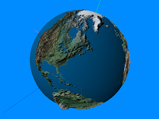
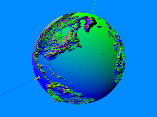
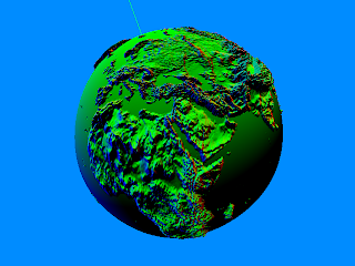
Obviously the terrain cubic heightmap I used was good 'ole Earth (and the heights are a bit exaggerated, ha). It looks pretty bland but what's important (at least right now) is what's going on under the hood.

The heightmap I used is a high-resolution (downsampled to 4096x4096) 16-bit tiff DEM based off of satellite scanned terrain data. Because DEM's are rectangular grid based by nature, I needed to find a way to transform a two dimensional topographical map into a cube map. To do this I created a nifty little program that takes a 2D rectangular image with a 2 to 1 proportion, maps it to a sphere using either a spherical or cylindrical projection, then renders the sphere from the inside out to a cube map. The result is taking something like this:

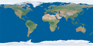
and converting it into this:


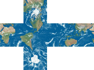
Notice how the cube is reversed? That's a byproduct of rendering from INSIDE the sphere and while it is correct, it can be easily corrected (if needed, i.e. if the object used a different uv mapping). The same process can be done to a heightmap, assuming we make sure to support 16/32-bit floating point colors to preserve that nice precision which can then be used to create the spherical terrain.

This is also super handy in cases where I want to use a cube map as opposed to a rectangular (sphere mapped) texture. Why would I want to do this you may ask? Well it turns out spherical textures exhibit some aliasing near the poles due to how the pixels are distributed to those areas. By using a cube map it is possible to use a lower resolution cube map to represent a much higher resolution 2D map with the same level of detail. The catch is that in benchmarks I've done the cube map performs slightly slower. I was a little surprised because although a rendering cube map can certainly be slightly costly if your ray samples are mostly random, texturing a sphere should be pretty cache friendly as the rays are all adjacent and basically wrap around the surface of the sphere (the texture coordinates are just a vector from origin to vertex, interpolated per-pixel). Perhaps there is an intrinsic cost to sample from face to face. Or maybe it's some kind of driver issue (when in doubt, blame the drivers :-). The other gotcha is that it's more difficult to stream in cube maps for very large worlds (if you were going in that direction).

It's also possible to do the reverse, albeit with some 2D processing as opposed to 3D. In other words, to convert a cube map to a 2D texture. I chose to implement this feature for the cases in which I wanted to procedurally generate a planetary texture that can be easily touched up and texture mapped in the traditional way. The transform is pretty simple and involves first calculating a polar coordinate for each pixel then transforming that into a cartesian vector that can sample the cube map. The sampled color then becomes the new color for that pixel. As an example, here is a random cube map I found on the internet:

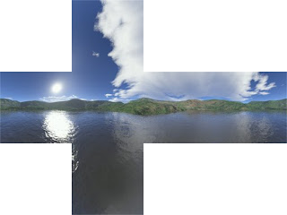
And here is how it looks converted to a sphere mapped texture.


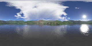
What a nice panorama! The nice thing with doing it this way is that supersampling (for nicely anti-aliased images) is easier to do by rendering at a higher resolution then downsampling to the desired size. It's not as simple with the cube render as you need some massive resolutions (which are still not so well supported on cube maps), plus, it's easy to run out of video card memory, ex: if you wanted to do a final render of a 32-bit 1024^2x6 texture at 4x supersampling you'd need 4096x4096x6x4 bytes per pixel = 384MB. For a 128-bit float heightmap it's 4 bytes per-CHANNEL, so 4096x4096x6x16 bytes = 1536MB!! This doesn't include the memory needed for your source assets or geometry buffers. :-)

A solution to this is to break up the texture into multiple blocks which are then saved out individually and later stitched together and resampled as a post-process. In the case of the cube map render you would just render each face to a texture. All of this is pretty unnecessary of course unless you're really trying to squeeze out some quality that may or may not come from such high resolutions.

Another nice thing that came out of this line of research was an elegant way to render a skybox using a cubemap on a single quad, that is to say two triangles that forms a square over the screen as opposed to say the 12 triangles required to actually draw a box. It's a nice little trick that takes advantage of the way in which the view transform relates to the 2D clip space screen plane. Even though it's 2D there is perspective as you rotate the view around. In addition I found a nice way to set the FOV. While nothing revolutionary, it's simple and elegant and probably prevents a stall or 2 in the pipeline somewhere. It also means I don't have to code up yet another box any time I want a skybox so I'm pretty happy about that.

Alright one more teaser to bow me out.

Thursday, July 16, 2009

Planetoids

This update is actually going to be referencing some older stuff I had been working on as I'm knee deep in finishing up a little iPhone app and don't really have anything interesting to show for it (it's a Blackjack game, woohoo...).

About 4 years ago I was playing quite a bit with procedural planet creation specifically using the techniques outlined in the book Texturing and Modeling: A Procedural Approach (a fantastic and highly recommended read for graphics programmers). What I was hoping to get from this was the ability to procedurally generate planets for the Star Trader universe, more as an offline tool to save time than as a real-time galaxy generator as some people have implemented. The results were very good and I ended up with a great tool to generate pretty decent looking planets completely on the fly for rapid iteration (utilizing perlin noise on the GPU in real-time). These could then be saved off to a cubemap and potentially converted to a spherical map (to be applied to the planetary spheres).

This tool has sadly been lost to the sands of time (I've adopted a much better project archiving system to avoid this) but my interest in creating procedurally generating planets hasn't vanished. Recently I revisted this from another viewpoint -- since the cube map can be used to represent a spherical environment, how could I take the planetary cube map I generated and turn that into an actual geometric representation instead of just using it as a texture. This isn't a very trivial thing to do considering terrains are normally fixed to a single ground plane.

My first attempt involved directly translating the faces of a cube map (painted with a hastily made noise based terrain and another with just the axis triad) to a cube, with each cube face as a seperate terrain. After this I applied a spherization formula that basically generates a unit (normalized) sphere, then, for each vertex, takes the sampled height value and outwardly projects it's position relative to that. Viola, a sphere made of six terrains (here's another option that also works but for some reason the results don't look as good to me: link). Here are some screenshots to demonstrate;


Getting the geometry in spherical form isn't the only thing that needs to be done. The normals must also be transformed from their original representation to the spherized version. This is the tricky part. After trying quite a number of techniques, Alex Peterson (thanks again Alex!!) pointed me to a great little article on building a rotation matrix from one vector to another. Since the original position and the new position are vectors, getting their rotation matrix and transforming the normal by that became a pretty trivial matter! You can find the article here. I'll post some screenshots of the final result next time.

Thursday, May 14, 2009

Shaders!

The past few months I've felt a new resolve to get Star Trader back on track and the main hurdle to this has been two technological uncertainties - the streaming system and the material system. The streaming system is not as big a priority as the game doesn't NEED it necessarily to proceed, but my material system is another matter all together.

My original intention was to build an advanced prototype of the new material system in-place with the old one so I can compare and contrast which is better and whether the old system has a place as a low-level fallback. If it worked better use it, if not, scrap it and fallback to the old with minimal effort. Theoretically this is a sound principal since it can be risky to fully commit to a system that has not yet been completed. In practice though things did not go as planned and in the future I will probably just create a separate branch which I can then integrate/merge to or throw away depending on the outcome.

In the end all my predictions were valid and having planned the system so thoroughly (over 10 pages of design notes with many more pages of format specs), it was unlikely that I missed something. The new system is better, plain and simple, and while I'm still really proud of the old system (comparably it's easier to use and more powerful than the material systems in some games I've worked on), gutting the old system code is going to be a necessary hassle. It's a shame because it was especially difficult implementing the new system around the old one. The best comparison I can muster is like navigating a maze overrun with sharp and pointy vines.

The new material system is essentially a node graph (DAG) that exists at three levels; Template, Definition, and Shader Tree. The Template represents the base logic from which shaders are generated as well as base states and parameter definitions. It's here that the user specifies node statements by utilizing a library of pre-existing "operators". The material Definition just overrides the properties of the existing parameters, allowing the same template to be reused with different arguments/states. The Shader Tree is where the real magic happens.

The tree is pretty straightforward except for the way in which it handles permutations. Essentially each level of the tree references a state, and each sibling node a state condition. A state might be 'Fog', and it's conditions 'On' or 'Off'. The tree for this would be relatively simple. In run-time the tree is traversed using the current state of 'Fog' to determine whether to use the 'On' or 'Off' shader. Things get interesting when we introduce more than one permutation. For instance, let's add a 'Point Light' state with 3 conditions; '0 lights', '1 lights', '2 lights'. For each state and all possible conditions, the tree is generated with a leaf node containing the actual procedurally generated shader (with all the accumulated state attributes/code). In this example we'd end up with a total of six shaders for all possible combinations of those state conditions.

Now sure, with current shader models it's possible to build all that logic into an 'uber-shader' of sorts, but from my experience, this is incredibly slow and inefficient. While a Set..Shader() call is not cheap (maybe half as bad as SetTexture()), conditional branching on a per-pixel level is, well, SLOW! A 720p screen resolution could potentially require 921,600 per-pixel conditional checks per render frame! By reducing the work load to the bare essentials via condition specific permutations, it's possible to save a tremendous amount of fill-rate, leaving us to do other interesting things.

Personally, I think graph based shader editors get a little too much attention. The big push for them seems to be from people who believe that exposing shader code visually will allow technical artists to create more interesting materials than little 'ole graphics programmer could. However, in my humble opinion (and taking into account some experience I've had with the subject), giving a technical artist that level of control usually leads to unexpected performance issues down the line and really doesn't elleviate the complexity required to make a graphically stunning effect in short time (thats what a good artist frontend like the "Definition" layer is for). The biggest reason I went in this architectural direction was for the ability to generate permutations which is much easier when you can break up your code into logical chunks, as graph based shader systems do. Having said all that, I don't mean to downplay the importance of a node editor since I really would prefer laying down nodes in a visual graph editor as opposed to adding them manually in a text file. That's actually my first priority after the GUI system is done, hehe.

Why are permutations so important? Anyone who's worked on a large enough project has experienced shader bloat to some degree or another. As an example, think of the shaders that light objects in a scene. Let's say you can light an object with up to 4 lights at once (optimally, with a 1-1 mapping). Well you're probably going to need at least the basic light types; point, spot, and directional/planar. That already puts you at 12 shaders (+1 for non-lit). What if you wanted to add fog? Environment mapping? An ambient occlusion term? Parallax bumpmapping? It can get pretty wacky to account for all of these things! For some people it's not a big deal, but, in my case where I like custom tailered shaders for unique effects it can get pretty out of hand.

So now with a good solution nearly complete I need to rebuild my shader library. The plan so far is to concetrate on a simple and elegant lighting solution that matches the stylized look of the game (remember those Invader Zim images)? Right now this means going back to Deferred Rendering. It's a fantastic algorithm despite being a little overhyped. It's much more efficient than your standard forward renderer, although saying that all your lighting is free (as I've heard from so many people) is ridiculus - you definitely pay the price for your light volumes and the per-pixel cost of evaluating all those lights (and if you want shadows you better be willing to pay the price). Despite this it really does allow you to display a very high level of quality at a reasonable price.

For my purposes I intend to use it to lay down a base layer as part of a two tiered rendering pipeline. If an object doesn't meet the criteria for being lit by the Deferred Renderer, it continues down the pipe to the Forward Renderer. The main benefit to using the Deferred Renderer has to do with the way I do my non-photorealistic lighting. Specifically I use something very similar to the G-Buffer in order to generate some nice outlines so it makes sense to leverage this into a full lighting solution. I'll also be able to more easily implement things like Depth-of-Field and Glare/HDR, although MSAA becomes a challenge. The Forward Renderer is required so I can draw objects that don't fall into the additively lit category (which actually happens to be quite a few things). I won't get the free inking/shading with it as I would with the Deferred Renderer but I'm hoping to find a solution that will work well for things like translucent lit objects.

I wish I had some interesting shots to show all this off but really it's just been a lot of engine work. The idea is to streamline the development process so unfortunetly this kind of feature doesn't lend itself well to screenshots. :-)

On the upside I do have some interesting things to show next time related to the terrain tools I've been working. More to follow in the coming weeks but until then, here's a teaser;

Tuesday, April 28, 2009

The Name Game Trap (TNGT?)

Marketing your game is usually a pretty drab affiar but when the developers get involved in marketing their technology, things get really interesting. Take Epic for instance and their proprietary Unreal Technology. They're up to version 3 now with 4 coming out relatively soon and their engine boasts a number of confusedly named components. Gemini, Cascade, Kismet, PhAT, Swarm, Matinee, and now Lightmass and MCP. If you've worked with Unreal Tech some of these may sound familiar, but if not, you're probably pretty confused right about now. Who would guess that Kismet is their visual scripting tool? Or that MCP (named after the antagonistic A.I. in Tron) would be their gameplay statistics tool.

It's an interesting brand marketing strategy especially since most companies just use acronyms. For Mark Rein it probably makes things easier for him to be able to spew out cool sounding names like PhAT or Swarm during a press event and I'm sure the public eats it up. For the developer interested in licensing their technology, does it really matter though? Sure, Matinee makes sense as their camera scripting tool but does cascade bring to mind at all particle systems and effects? Does it describe in any coherent way what it as feature does or how it can be utilized? The value it brings to a project?

We did something similar at Raven with names like Icarus (our scripting system), behavEd (the scripting system editor), Ghoul (the dynamic dismemberment system), confuseEd (dynamic object destruction), vertigons (surface sprites), etc... In the end it  becomes something cumbersome and annoying to have to deal with the ambiguity but it does add a bit of extra flavor to an otherwise drab sounding feature.

At id, naming engine iterations with the idTech prefix makes a whole helluva lot of sense but outside of a few interestingly named systems (like AAS - area awareness system), the idTech 5 renderer is just, the renderer, not Lightning or Talon or some other pointy sounding name.

At home I tend toward the simplistic. Right now the engine I've been developing on and off the past 9 years is called the AREngine (which I do plan to backronym as some point). I'm just finishing up a shader graph based permutation system which I blandly call MaterialV2 (Material version 2, despite this being the 4th iteration of my material system - it's the first one I've developed in-place with the previous still functional). Here is a feature that could be a key selling point of the engine and it ends not in an exclamation mark but a period.

If you want to get excited about what you're working on (and get other people excited as well) you usually have to add a bit of edge, which is I think what Epic has done. Having said that, attaching a catchy name that represents what a feature is about is the hard part. The easy part is falling into the name game trap.

Tuesday, March 31, 2009

Polymorphic Excision

Usually when I'm getting back into a codebase, I'll pick a small project and latch onto that until it's completed. This is a great way to re-orient yourself with a once familiar codebase that you've become rusty with. Lately I've jumped back into my millenias old Star Trader project and decided to do just this.

A while back there was a great presentation at one of the Microsoft Gamefest events titled "Cross-Platform Graphics Engine Development". The premise of this talk was that excessive use of OOP features (like Polymorphism) is harmful when building a system that relies on maximum performance and thus such a system should be tailored to use a more direct approach utilizing type definitions (as opposed to polymorphic type abstraction). What this means in the end is instead of keeping a hierarchy of inherited interfaces to something like your renderer, just create a new type dependent on your platform (and API of choice) and link it in. This is precisely what I decided to do.

Now I'm not the type that buys into the argument that C++ is incredibly slower than C, but in general, using a feature needlessly while paying the cost is just, well, dumb. The way my code was I had a 3 teir inheritance hierarchy with the interface at the bottom, the shared functionality (ex. state tracking) at the middle, and the API implementation (D3D9, OpenGL, ...) at the top.  This allows me to derive the common interface to generate any number of API implementations and link them in as a DLL. This works pretty well but I'm nearly certain I will never be swapping out my renderer on the same platform (Win32,  MacOSX, PS3...). I was paying for a feature I will never use.

To resolve this, I first compiled the renderer as a static library. After this, I came up with a public interface to the renderer, that, based on platform and project settings will access only the primary accessor to the renderer. In addition I broke off the common behavior into it's own object that the API specific code calls as neccessary. This was all pretty straightforward and the main executable now directly links to the API specific Renderer. When I create additional platform/API implementations, the interface can still be enforced with a conditional inheritance of the base level interface to ensure that everything was implemented properly (a nice trick). Just to be thorough, I did go ahead and implement an additional option that allows a DLL to be loaded with an inherited renderer (as before), so I could do something like release a Direct3D 11 renderer for those that supported it down the line. Personally I don't like doing stuff like that (you're basically bandaging on functionality and resources at that point instead of building it in to the initial overarching plan), but I figured what the heck.

I was quite surprised at the ease of this switch. That is of course until I started the game and my resource manager puked on me. :-)

I really enjoy using pluggable software factories. I enjoy them so much I use them exclusively for declaring resource type allocators to my resource manager. In a one line macro, I can completely register a resource class and know that I did it right. It's fantastic and despite the use of Macro's and Globals, I think it's a very elegant solution. Coupling is reduced to nearly nothing since the definition, implementation and registration can all happen in the same .cpp file. I'll spare you the details but here is a link to a good explanation of pluggable factories.

Since it's a solution that exists in global scope, it does come with it's caveats. Initialization in global scope is seemingly random, so how do you control the order of initialization so that the list of resource allocators is not re-initialized to empty AFTER having already added elements to it? The solution to this is actually quite simple though you won't find it in too many programming books. Using lazy evaluation (also known as Construct On First Use), I ensure the list is initialized only on it's first call. This is really easy to implement and merely consists of using a static variable (of the list) within the scope of a function. The first time the function is called to get the list is when the list is initialized. It would look something like this:
CResourceAllocatorList *GetResourceAllocatorList()
{
    static CResourceAllocatorList s_ResourceAllocatorList;
    return &s_ResourceAllocatorList;
}

To use it:
GetResourceAllocatorList()->Append( pNewAllocator );

This works great in practice and like I said, is super convenient. When these are defined in a DLL, they sit there waiting until the DLL is created and as soon as that happens are initialized and registered. Eventually they do have to be collected (since the DLL has it's own heap) but this is easy enough and if you use a linked list it's as easy as linking the allocator as another node. But what happens when you link these in via a static library? Nothing... nothing at all. If a factory is placed in a file that has no external references, the linker will omit a reference to the compiled object file when linking it in to the executable. This effectively means that your factories will NEVER be registered. That's, well, really bad! While Visual Studio does have an option to never remove unreferenced data (which should probably never be used), it doesn't actually work for data removed due to an .obj being unreferenced (this is supposedly intended behavior).

Resolving this issue is naturally a pain in the ass. One way is to look at your list of generated symbols, find the decorated name for your factory and include a pragma line that forces inclusion of that symbol in the linker, i.e.
#pragma comment( linker, "/include:?blah@@" )

This is incredibly annoying and completely destroys the convenience of using a factory in the first place. Another way is to include some kind of reference to that file or your factory in code that is definitely executed (like main() or your primary initialization routine). This is what I ended up doing but in a semi-automatic way. I made a Macro in which you pass in the resource type name (RESTYPE_TEXTURE, RESTYPE_MODEL, etc...) and a reference is automatically generated for you (calling a dummy function in an automatically generated pointer to the base factory type, initialized when the factory is created). This effectively adds an additional step to the process but at least it's somewhat straightforward, as opposed to the other option.

After that everything was working perfectly! I still have to do some performance tests to double check that talks premise (of sacrificing flexibility for performance) but at first observation the program does appear to have a smaller memory footprint (likely due to the additional optimization the compiler/linker does thanks to the file being directly linked in and the exclusion of some v-tables).

All in all it was a nice little exercise that definitely got me re-acquainted with my old codebase. Next up on my radar is finishing up my new shader system. I'll talk more about it some other time.

Friday, March 6, 2009

The Big Move!

The response to the interviewing article went really well! I got a lot of great comments about it and am really glad I was able to give back a little by contributing a piece like that. Hopefully I'll find some time to write more articles like it in the future.

So the past few months have been pretty interesting for me. A few months ago I made the decision to leave Destineer to work for id Software. They're a great company and everyone there is absolutely awesome but I just could not pass up the chance of a life time to work at the company that got me excited about computers and games in the first place! They were all incredibly understanding and I truly wish them the very best. Trust me when I say they're working on something really amazing and I'm very excited to see the final result!

So outside of that I've been keeping pretty busy. While looking for some code to generate cubic noise maps (as part of a series of new experiments I've been working on to generate spherical terrains) I ran into my old starfield generator which generates random points and "blurs" them as they whiz by you. A very cool effect, especially when you consider how the points were generated.

When you generate random noise around a unit sphere you have to be incredibly careful to ensure that they are uniform, otherwise you'll see them gathering towards one of the poles as demonstrated here:


The problem lies in how spherical coordinates tend to congregate points towards the poles. To fix this problem you can use sphere picking to ensure any given area around the sphere contains the same number of points:
This may seem relatively trivial and unimportant for something like a starfield (which it is), but where it starts to really matter is when you need to generate random vectors for something like raytracing. I recently created an ambient occlusion generator for heightfields and ran into an issue where the sampled values where resulting in way to many false positives than they should have been. As I'm sure you can imagine, the issue is pretty obvious; most of the generated rays were going straight up, and heightfields by definition do not have overhangs for those rays to hit!!! The simplest solution is to scale the generated rays up value so they go more towards the sides (which helps quite a bit), but really the best way to do it is to properly generate the sampling rays around the unit hemisphere uniformly. By doing this I was able to get away with using a lot less rays for fantastic looking results!

I won't bother to provide the full algorithm here but if you're interested, check out this page: Sphere Point Picking.


So as I mentioned I've been doing quite a bit with terrains. Unfortunately I don't have much to show as far as screenshots as it's been mostly experimental type stuff to learn and get acquainted with new algorithms. After I finished the ambient occlusion generator I went ahead and wrote a lightmapper for fun (it wasn't that much of a departure) and started a survery of terrain shadowing techniques.

Shadow Mapping is a tried and true classic which can give some great results if you're willing to put a little blood and sweat into your implementation (ala CSM's, VSM's, TSM's, etc...). Lightmapping is nice but only works for static terrains and doesn't work so well for dynamic objects (though I know of some neat tricks to fix this). Ambient Occlusion works nice but only works for global indirect light (so is more complementary than comprehensive). Spherical Harmonics is an option but from my research doesn't always result in the best looking shadows.

One experimental shadowing technique I tried which resulted in some really nice soft-shadows is Ambient Aperture Mapping. The idea behind it is pretty novel and is similar to relief mapping but simpler. First, you generate your aperture values which consist of a bent normal; a vector pointing towards an un-occluded light source (i.e. the sky/sun/moon), and the aperture; essentially a circle at the end of the bent normal which defines how much light reaches that point (this value is similar to an ambient occlusion result and make the bent normal into a sort of cone). After you have these you can test any given terrain surface point's aperture against your global light source which has it's own aperture values. The intersection of these two apertures defines how much light reaches that surface point.

The results are surprisingly good! I may utilize this in full force the next time I need an efficient low to medium frequency shadowing solution with modest storage costs for terrain rendering. Here's a paper on it for your reading pleasure: Ambient Aperture Lighting, and a screenshot of their results:


That's enough for now. Until next time!